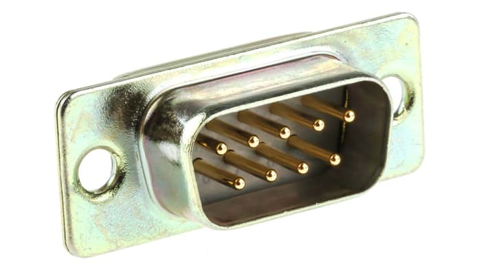
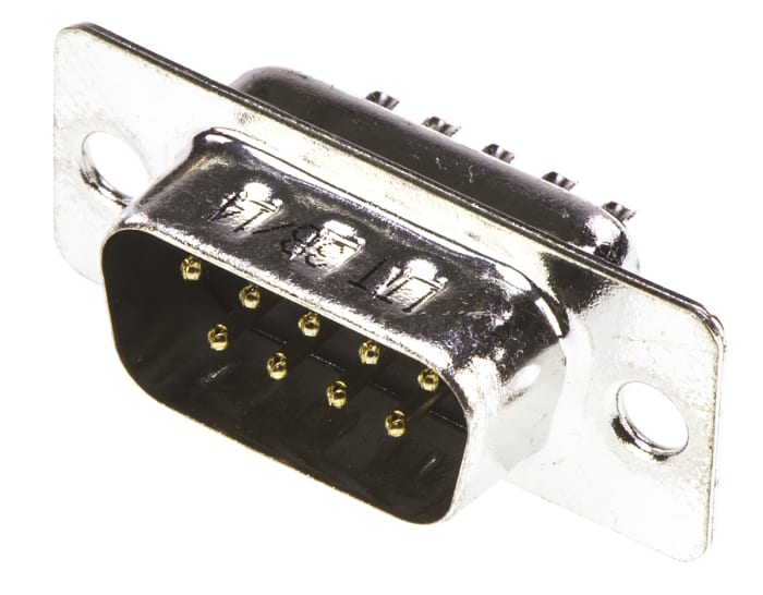
RS PRO 9 Way Panel Mount D-sub Connector Plug, 2.74mm Pitch

Technical documents
Specifications
Brand
RS ProNumber Of Contacts
9
Gender
Male
Body Orientation
Straight
Mounting Type
Panel Mount
Pitch
2.74mm
D Connector Type
Standard D-Sub
Termination Method
Solder
D-Sub Shell Size
E
Current Rating
5.0A
Current Rating
5A
Housing Material
Steel
Voltage Rating
750.0 V
Length
30.81mm
Width
12.55mm
Depth
14.67mm
Dimensions
30.81 x 12.55 x 14.67mm
Contact Plating
Gold Flash
Contact Material
Copper Alloy
Minimum Operating Temperature
-65.0°C
Maximum Operating Temperature
+125°C
Country of Origin
United Kingdom
Product details
RS PRO High-Performance D-Sub Connector with Bright Tin Plating and Solder Cups
From RS PRO a high-performance D-Subminiature connector with a bright tin plated steel shell with grounding indents for EMI and RFI shielding. Solder cup terminations on the rear of this connector allow the easy connection of wires. These D-sub connectors have an RS232 standard interface and conform to BS9523 F0010 and F0018. The pins of this subminiature connector are machined to a high quality and feature flanges with pre-drilled 3.05mm diameter holes on either side for easy panel mounting. These d-sub connectors are ideal for use in for I/O (input/output) interconnections in a wide range of industrial and commercial applications.
What is a D-Sub Connector?
A D-Sub connector is a popular type of I/O connector that is commonly used in the computer and datacoms industry to provide power and point-to-point communications between two devices such as a computer and a monitor. The d-sub contains two or more parallel rows of pins or sockets surrounded by a D-shaped metal shell which provides mechanical support and ensures the correct orientation is used when mating. These d-subs are available as female D-sub sockets (or d-sub receptacles) with female contacts or male D-sub plugs with male pin contacts. The socket style female connector mates with the plug style male connector. Please note that a D-sub with a plastic shell cannot be mated with a D-sub with a metal shell.
Features and Benefits
• High performance design
• Performance Level 3
• RS232 standard interface
• Robust bright tin plated steel shell with grounding indents for EMI and RFI shielding
• Machined contacts
• UL 94V-0 insulator
• Flanges containing 3.05 mm mounting holes for screw mounting to a panel
• Solder cups for simple wire termination
Applications
This d-sub connector with its robust design can be used in communications and network ports in a wide range of industries including industrial, commercial and medical. Applications include the following:
• Computers, monitors and scanners
• Networking and communications equipment
• Data processing equipment
• Industrial equipment
• Test and measurement instrumentation
• Remote sensors and dataloggers
• Portable electric generation equipment
Frequently Asked Questions
How do you terminate the wires into the connector?
These d-subs feature solder cups which are hollow cup-like cavities into which the wire is inserted and secured by soldering. Firstly make sure the connector is held securely while working on it. Strip the ends of each wire using the depth of solder cups to gauge how much insulation you need to remove. Tin the exposed strands with a soldering iron and partially fill the solder cup with solder. Apply a soldering iron to the edge of the cup allowing the solder to melt. Insert the end of the tinned wire into the cup and hold it in place until the solder becomes solid. If the wire gauge is large enough to support itself in the cup place it in the cup and feed in the solder whilst applying the soldering iron to the back of the cup.
How do you mount these connectors?
These d-subs are designed to be panel mounted. A hole is cut in the panel which is determined by the panel cut-out dimensions of the plug or socket. Two flanges either side of the connector incorporate 3.05mm mounting holes. Holes are drilled into the panel to align with these holes. The connector is then inserted into the panel cut-out and secured in place by inserting screws through the holes in both the connector and panel.
Standards
Conforms to BS9523 F0010 and F0018
Meets dimensional requirements of MIL-C-24308, BS9523 F0018 and DIN 41652
High Specification & Aerospace & Industrial Connectors
P.O.A.
1
P.O.A.
Stock information temporarily unavailable.
1
Stock information temporarily unavailable.
| quantity | Unit price |
|---|---|
| 1 - 24 | P.O.A. |
| 25 - 99 | P.O.A. |
| 100 - 499 | P.O.A. |
| 500 - 999 | P.O.A. |
| 1000+ | P.O.A. |
Technical documents
Specifications
Brand
RS ProNumber Of Contacts
9
Gender
Male
Body Orientation
Straight
Mounting Type
Panel Mount
Pitch
2.74mm
D Connector Type
Standard D-Sub
Termination Method
Solder
D-Sub Shell Size
E
Current Rating
5.0A
Current Rating
5A
Housing Material
Steel
Voltage Rating
750.0 V
Length
30.81mm
Width
12.55mm
Depth
14.67mm
Dimensions
30.81 x 12.55 x 14.67mm
Contact Plating
Gold Flash
Contact Material
Copper Alloy
Minimum Operating Temperature
-65.0°C
Maximum Operating Temperature
+125°C
Country of Origin
United Kingdom
Product details
RS PRO High-Performance D-Sub Connector with Bright Tin Plating and Solder Cups
From RS PRO a high-performance D-Subminiature connector with a bright tin plated steel shell with grounding indents for EMI and RFI shielding. Solder cup terminations on the rear of this connector allow the easy connection of wires. These D-sub connectors have an RS232 standard interface and conform to BS9523 F0010 and F0018. The pins of this subminiature connector are machined to a high quality and feature flanges with pre-drilled 3.05mm diameter holes on either side for easy panel mounting. These d-sub connectors are ideal for use in for I/O (input/output) interconnections in a wide range of industrial and commercial applications.
What is a D-Sub Connector?
A D-Sub connector is a popular type of I/O connector that is commonly used in the computer and datacoms industry to provide power and point-to-point communications between two devices such as a computer and a monitor. The d-sub contains two or more parallel rows of pins or sockets surrounded by a D-shaped metal shell which provides mechanical support and ensures the correct orientation is used when mating. These d-subs are available as female D-sub sockets (or d-sub receptacles) with female contacts or male D-sub plugs with male pin contacts. The socket style female connector mates with the plug style male connector. Please note that a D-sub with a plastic shell cannot be mated with a D-sub with a metal shell.
Features and Benefits
• High performance design
• Performance Level 3
• RS232 standard interface
• Robust bright tin plated steel shell with grounding indents for EMI and RFI shielding
• Machined contacts
• UL 94V-0 insulator
• Flanges containing 3.05 mm mounting holes for screw mounting to a panel
• Solder cups for simple wire termination
Applications
This d-sub connector with its robust design can be used in communications and network ports in a wide range of industries including industrial, commercial and medical. Applications include the following:
• Computers, monitors and scanners
• Networking and communications equipment
• Data processing equipment
• Industrial equipment
• Test and measurement instrumentation
• Remote sensors and dataloggers
• Portable electric generation equipment
Frequently Asked Questions
How do you terminate the wires into the connector?
These d-subs feature solder cups which are hollow cup-like cavities into which the wire is inserted and secured by soldering. Firstly make sure the connector is held securely while working on it. Strip the ends of each wire using the depth of solder cups to gauge how much insulation you need to remove. Tin the exposed strands with a soldering iron and partially fill the solder cup with solder. Apply a soldering iron to the edge of the cup allowing the solder to melt. Insert the end of the tinned wire into the cup and hold it in place until the solder becomes solid. If the wire gauge is large enough to support itself in the cup place it in the cup and feed in the solder whilst applying the soldering iron to the back of the cup.
How do you mount these connectors?
These d-subs are designed to be panel mounted. A hole is cut in the panel which is determined by the panel cut-out dimensions of the plug or socket. Two flanges either side of the connector incorporate 3.05mm mounting holes. Holes are drilled into the panel to align with these holes. The connector is then inserted into the panel cut-out and secured in place by inserting screws through the holes in both the connector and panel.
Standards
Conforms to BS9523 F0010 and F0018
Meets dimensional requirements of MIL-C-24308, BS9523 F0018 and DIN 41652

